
TL;DR and Key takeaways:
- SMD component sizes use a four-digit code for the part’s length and width. Imperial codes read in hundredths of an inch (0603 = 0.06 in × 0.03 in = 1.6 mm × 0.8 mm); metric codes read in tenths of a millimeter.
- The classic trap: imperial 0603 and metric 0603 are different parts. Metric 0603 is the tiny imperial 0201. Always confirm which system a datasheet or BOM is using before you order.
- Hand-solder reality: 0805 and 0603 are comfortable, 0402 is fine with practice and flux, and 0201 is tweezers-and-hot-air territory. Below that, plan for a stencil and reflow.
- Resistors and capacitors share the code system but differ in what they carry: resistors scale power with body size (0402 ≈ 1/16 W up to 2512 ≈ 1 W); capacitors vary in height and available value per case.
- Smaller is not automatically better: Power and voltage ratings drop, placement tolerance tightens, and assembly yield falls as the package shrinks. Pick the largest package your layout can afford.
You know how bad it feels when your prototype gets held up just because you picked the wrong component size, and now you can’t even solder it onto the board?
I learned this lesson pretty early in my electronics journey. Just to save a bit of board space, I happily specified 0201 components without giving much thought to assembly. That tiny “space-saving” decision quietly turned a board I could have soldered by hand into one that needed a stencil and a reflow oven, none of which I’d budgeted for.
Package size is one of the earliest choices in a design, and it sets your board density, your assembly method, and how repairable the thing is at 2 a.m. before a demo. This guide gives you the numbers you came for, a clean metric-to-imperial chart with real dimensions for resistors and capacitors, and then the part most size charts skip: an honest bench view of who can hand-solder what.
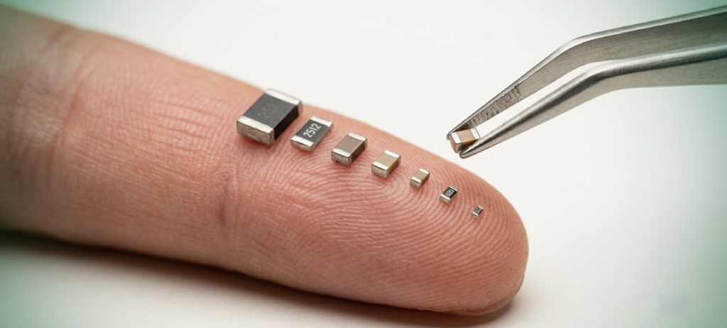
A visual comparison of common SMD package sizes — from the tiny 0201 to the larger 1206.
How SMD Size Codes Work
A surface-mount chip component, such as a resistor, ceramic capacitor, or small inductor, is a rectangular block with metallized end caps. Its “size” is a four-digit code built from just two measurements: length and width. The code describes the body form factor only. It tells you nothing directly about power rating, voltage rating, or the copper land pattern you have to draw.
The confusion starts because two different coding systems use the same style of number:
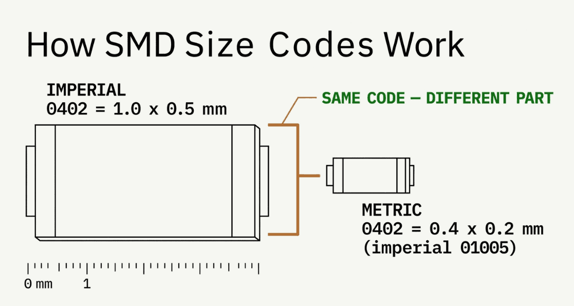
How the four-digit SMD size code encodes length and width in both imperial and metric systems.
Imperial code — length and width in hundredths of an inch. So `0805` means 0.08 in × 0.05 in.
Metric code — length and width in tenths of a millimeter. So `2012` means 2.0 mm × 1.25 mm (rounded).
And the fact is: imperial 0805 and metric 2012 are the same physical part. US distributors mostly speak imperial in casual conversation (“hand me an 0603”), but many European datasheets and some CAD libraries default to metric. That tiny naming mismatch is responsible for countless wrong part orders.
The 0402/0603 collision:
This is the trap that costs people a build.
- Imperial 0402 = a 1.0 × 0.5 mm part = metric 1005.
- Metric 0402 = a 0.4 × 0.2 mm part = imperial 01005 (one of the smallest component parts that exists on earth)
- Imperial 0603 = 1.6 × 0.8 mm = metric 1608.
- Metric 0603 = 0.6 × 0.3 mm = imperial 0201.
This is the trap that costs people a build.
If a footprint or bill of materials just says “0603” with no unit, treat it as ambiguous until you confirm the source’s convention. We recommend writing the metric code explicitly in BOM notes for anything below 0603 imperial, where a mix-up is unrecoverable by hand.
SMD Size Chart: Every Common Package
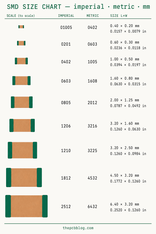
This is the fast-lookup table. Dimensions are nominal for standard chip resistors and MLCC capacitors; individual datasheets vary by a few hundredths of a millimeter. It runs from the exotic 01005 up to the workhorse power sizes at 2512.
| Imperial code | Metric code | Length × Width (mm) | Length × Width (in) | Typical uses |
|---|---|---|---|---|
| 01005 | 0402 | 0.4 × 0.2 | 0.016 × 0.008 | Ultra-dense mobile/wearable RF |
| 0201 | 0603 | 0.6 × 0.3 | 0.024 × 0.012 | High-density phones, modules |
| 0402 | 1005 | 1.0 × 0.5 | 0.040 × 0.020 | Standard dense boards |
| 0603 | 1608 | 1.6 × 0.8 | 0.063 × 0.031 | Prototypes and production |
| 0805 | 2012 | 2.0 × 1.25 | 0.079 × 0.049 | Hand-friendly small part |
| 1206 | 3216 | 3.2 × 1.6 | 0.126 × 0.063 | Higher-power passives |
| 1210 | 3225 | 3.2 × 2.5 | 0.126 × 0.098 | Higher-capacitance MLCC |
| 2010 | 5025 | 5.0 × 2.5 | 0.197 × 0.098 | Power and current-sense resistors |
| 2512 | 6332 | 6.3 × 3.2 | 0.248 × 0.126 | High-power (1 W+) and shunt resistors |
How to read it: the imperial and metric columns describe the same physical part in two languages. Note again that the metric code of one row often equals the imperial code of a smaller row; that overlap is the source of the collision above. When in doubt, trust the millimeter dimensions, not the code.
Want this as a reference on your bench? We render this master table as a shareable size-chart graphic – save it or pin it near your rework station.
SMD Resistor Sizes and Power Ratings
For chip resistors, body size does more than set board area; it sets how much heat the part can shed. A bigger body has more surface area and more copper contact, so its power rating climbs with size. The figures below are typical starting points for general-purpose thick-film resistors; high-power and pulse-rated parts exist in the same bodies, so always check the specific datasheet.
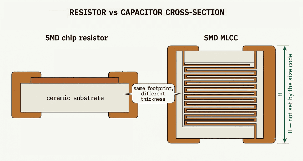
SMD resistor vs capacitor cross-section: same footprint code, different internal construction.
| Imperial code | Metric code | Typical power rating |
|---|---|---|
| 01005 | 0402 | 1/32 W (0.031 W) |
| 0201 | 0603 | 1/20 W (0.05 W) |
| 0402 | 1005 | 1/16 W (0.063 W) |
| 0603 | 1608 | 1/10 W (0.1 W) |
| 0805 | 2012 | 1/8 W (0.125 W) |
| 1206 | 3216 | 1/4 W (0.25 W) |
| 1210 | 3225 | 1/3 to 1/2 W |
| 2010 | 5025 | 3/4 W |
| 2512 | 6332 | 1 W and up |
Derating matters: Those ratings usually assume roughly 70 °C ambient; above that, the safe power falls along the manufacturer’s derating curve, typically reaching zero near 155 °C. Our rule of thumb: size resistors for the actual dissipation with a margin.
SMD Capacitor Sizes
Capacitors use the same code system as resistors; a 0805 capacitor has the same 2.0 × 1.25 mm footprint as an 0805 resistor. What differs is the trade-off the case size represents. For a multilayer ceramic capacitor (MLCC), a given code caps how much capacitance and voltage you can pack in: more layers or a thicker dielectric means either a bigger body or a compromise on one of the other specs.
| Imperial code | Metric code | Typical MLCC capacitance range | Typical voltage classes |
|---|---|---|---|
| 0201 | 0603 | 0.5 pF – 0.1 µF | 4 V – 25 V |
| 0402 | 1005 | 0.5 pF – 2.2 µF | 6.3 V – 50 V |
| 0603 | 1608 | 1 pF – 10 µF | 6.3 V – 100 V |
| 0805 | 2012 | 10 pF – 22 µF | 6.3 V – 250 V |
| 1206 | 3216 | 100 pF – 100 µF | 6.3 V – 500 V+ |
| 1210 | 3225 | 1 nF – 100 µF | 6.3 V – 1 kV+ |
Note: In Class II dielectric like X7R, remember capacitance falls with applied DC bias (a 10 µF part can behave like 3 µF at rated voltage), and never assume a smaller body holds the same value as its bigger sibling.
Why capacitor height matters
Here is the spec the four-digit code hides: height is not part of the code. Two 0805 capacitors can share a footprint while differing in thickness, ranging from about 0.6 mm to 1.4 mm. Because height depends on the internal layer count, and layer count is set by the capacitance you need. Height is generally not standardized the way length and width are.
That matters for two reasons. First, clearance under shields, connectors, and stacked boards, because a taller cap that works fine in the lab may cause problems with a shield in the final build. Second, tall, thin ceramics are more prone to flex cracking when bent, which is why some designs specify low-profile parts or keep caps away from board edges and mounting points.
Tantalum capacitors handle this differently: they use EIA case codes A/B/C/D instead of the chip code, and each is a defined length × width × height. The standard mapping:
| Case code | EIA metric size | L × W × H (mm, nominal) |
|---|---|---|
| A | 3216-18 | 3.2 × 1.6 × 1.6 |
| B | 3528-21 | 3.5 × 2.8 × 1.9 |
| C | 6032-28 | 6.0 × 3.2 × 2.5 |
| D | 7343-31 | 7.3 × 4.3 × 2.8 |
If a schematic calls for a “case B tantalum,” that is a fully specified footprint and height. So there is no unit ambiguity, unlike the chip codes above.
SMD Diode Packages in Brief
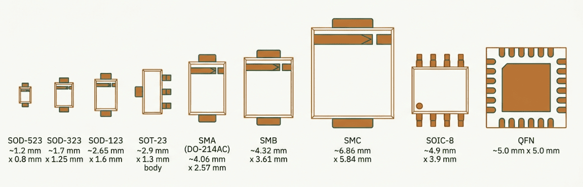
Once you leave two-terminal passives, the four-digit code disappears, and named JEDEC packages take over. SMD diodes typically use the SOD (Small Outline Diode) package family, which is designed for compact signal and switching diodes.
- SOD-123 (2.8 × 1.6 mm)
- SOD-323 (2.6 × 1.3 mm)
- SOD-523 (~1.6 × 0.8 mm)
Power rectifiers use the DO-214 family, better known as SMA (DO-214AC), SMB (DO-214AA), and SMC (DO-214AB), in ascending order of size.
Diode packaging is a topic in its own right, with polarity marking, thermal pads, and current ratings all varying by case, and we will give it a dedicated post.
SMD Transistor and IC Packages in Brief
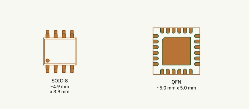
SMD IC package overview: QFN, SOIC, and SOT variants with size context.
- SOT-23 — the classic three-lead transistor/small-IC package, roughly 2.9 × 1.3 mm, with SOT-2,3,5 and 6 variants adding leads. They are hand-solderable with a fine tip.
- SOIC — small-outline IC with gull-wing leads on a 1.27 mm pitch; the friendliest IC package to hand-solder.
- QFN — a leadless package with pads under the body and usually a central thermal pad. Compact and thermally good, but reflow-only for reliable joints.
Which SMD Sizes Can You Hand-Solder?
Charts rarely tell you the thing you actually need at the bench: can I place this with an iron and tweezers, or do I need paste and heat? Here’s our honest ranking, based on countless hours of assembling and reworking PCBs with nothing more than a temperature-controlled soldering iron, a fine conical tip, plenty of flux, and a good pair of tweezers.
| Package (imperial) | Difficulty | What you need | Notes |
|---|---|---|---|
| 1206 / 2010 / 2512 | Easy | Any iron, basic tip | Large pads, very forgiving; good for power parts |
| 0805 | Easy | Standard iron, flux | The most beginner-friendly “small” part |
| 0603 | Comfortable | Fine tip, tweezers, flux | The practical sweet spot for prototypes and kits |
| 0402 | Doable with practice | Sub-2 mm tip, sharp tweezers, magnification | Routine once your flux discipline is solid |
| 0201 | Very hard | Tweezers, hot air/paste preferred | A few by hand under a microscope |
| 01005 | Impractical by hand | Stencil + solder paste + reflow | Effectively a machine-only part |
A few rules that fall out of this, learned the tedious way:
If you will hand-build or repair it, design with 0603 and 0805. You will thank yourself during rework, and inspection is realistic with a loupe rather than a microscope.
- 0402 is a genuine hand-solder size preferred for standard on dense boards. But budget for magnification and disciplined flux. Tin one pad, place the part, reflow that end, then do the other.
- At 0201 and below, commit to a process. Reach for hot air or a stencil and reflow profile, not an iron.
As the parts shrink and pad heating goes uneven on one end of a passive standing up during reflow, this effect is known as Tombstoning. It is the number-one small-package failure mode, and we will cover fixes in a dedicated piece.
Choosing SMD Package Sizes for Your Layout
Package selection is a three-way balance between density, yield, and cost. The honest advice is to pick the largest package your layout can afford, not the smallest available.
- Density. Smaller components definitely open up more routing channels and help shrink the PCB, but the benefits taper off quickly. Moving from 0603 to 0402 usually gives you a worthwhile space saving.
- Yield. Every step down tightens placement tolerance and stencil aperture design. Below 0402, expect a measurable rise in tombstones, mid-chip solder balls, and misregistration unless your process is optimized.
- Cost. The component is almost never what drives the cost. The process does. As packages get smaller, the manufacturing window gets tighter. You need finer stencils, more controlled reflow profiles, and better placement accuracy.
Check your assembly house’s minimum placeable size before jumping into the design. Many hand-assembly and low-cost lines top out at 0402 or 0201; going smaller can push a job to a different line entirely.
So when does 0201 (or below) earn its place?
When the board is genuinely space-constrained, such as a smartwatch, a hearing aid, a dense RF front-end, and you are already committed to full machine assembly with stencil, paste, reflow, and inspection. The smaller the part, the fewer particles around it, so the precision applications like RF love these smaller parts. But on a hobby board or a low-volume prototype that a human will place and repair, that same 0201 just wastes money and burns bench time.
Frequently Asked Questions
Q. What are the standard SMD component sizes?
The common imperial chip sizes, smallest to largest, are 0201, 0402, 0603, 0805, 1206, 1210, 2010, and 2512, with the exotic 01005 below them. Each is a length × width code: 0805, for example, is 0.08 × 0.05 inches (2.0 × 1.25 mm). See the master chart above for metric equivalents and dimensions.
Q. Is 0603 metric or imperial?
Both codes exist and mean different parts, which is the classic trap. Imperial 0603 is a 1.6 × 0.8 mm part, equal to metric 1608. Metric 0603 is a much smaller 0.6 × 0.3 mm part, equal to imperial 0201.
Q. What is the smallest SMD size?
In common use, the smallest is 01005 imperial (metric 0402), measuring just 0.4 × 0.2 mm; it is smaller than a grain of coarse sand. Even tinier parts, such as 008004, exist for cutting-edge mobile assembly, but they are exotic, machine-only, and rare outside high-volume consumer products.
Q. What SMD size is best for hand soldering?
For comfort and reliable joints, 0805 or 0603 are the sweet spot, and they are large enough to place with tweezers and a fine-tip iron, and easy to inspect. 0402 is very doable with practice, good flux, and some magnification. Below 0402, hand soldering becomes impractical; plan for hot air or a stencil-and-reflow process instead.
Q. Are SMD resistor and capacitor sizes the same codes?
They share the same four-digit code system, so an 0805 resistor and an 0805 capacitor have the same footprint. The difference is what each spec carries: resistor power rating scales with body size, while capacitors vary in height and in the capacitance and voltage available per case.
Q. What size are SMD diodes?
Small-signal SMD diodes commonly use the SOD family: SOD-123 (2.8 × 1.6 mm), SOD-323 (2.6 × 1.3 mm), and SOD-523 (1.6 × 0.8 mm). Power rectifiers use the DO-214 family, better known as SMA, SMB, and SMC, in ascending order of size.
The Takeaway
The four-digit code on a chip part is really two decisions in disguise: how dense your board will be, and how you plan to build and repair it. Get the metric-versus-imperial reading right, pick the largest package your layout can afford. Also, remember that capacitors hide a third dimension, “height” that the code never shows.
For related decisions, see our guides on through-hole vs SMD components, standard PCB thickness, the difference between PCB and PCBA, and annular ring rules for reliable vias.
If you’re building hardware and need technically accurate content for your company, we also create engineering blogs, application notes, and educational resources written by working PCB engineers.
Our goal is to help electronics companies publish content that engineers actually trust and search engines reward. Want to see the difference engineer-written content can make? Start with a free pilot article of up to 1,200 words, tailored to your website and written by working PCB engineers. More about how we work: services & pricing.