
TL;DR — the verdict up front
- Reach for SMD for size, unit cost at volume, or automated assembly — the default for almost every modern board.
- Reach for through-hole when a part takes mechanical abuse: connectors, jacks, big electrolytics, transformers, high-vibration, or high-power parts.
- Most real boards mix both: The question is rarely “one or the other” — it’s “which part, and why.”
- SMD ≠ SMT: SMD is the device; SMT is the technology that places it. Related, not interchangeable.
- Watch the process cost, not the part cost: A THT connector is cheap; the wave-solder step it forces onto an all-SMD board is not.
- One line: SMD wins on size, cost, and automation; through-hole wins on mechanical strength and raw power handling. That trade-off drives every decision below.
Surface-mount devices and through-hole components are a friendly battle of two component types. I say this because when I’m designing a board for hobbyists or students, I usually lean towards through-hole components. Not because I love them more, but because they’re simply easier to work with. Most people can solder them with a basic iron, and that makes the project far more approachable. Seeing someone build one of my boards successfully is genuinely satisfying.
On the other hand, if I have to design for production, I will choose SMD components because they can be assembled quickly and repeatably with pick-and-place machines. And they are easy to solder under reflow ovens. Automated inspection handles the assembly far more efficiently than any human could.
Although there are some cases where most of the engineers don’t choose between through-hole and SMD for the whole board, the choice is made component by component, based on the application. I’ve designed plenty of boards that are mostly SMD but still use through-hole connectors, large power inductors, and transformers.
That’s exactly how this guide is structured. We’ll start with the practical decision of what I’d choose for a given situation, and then explain the engineering reasons behind it.
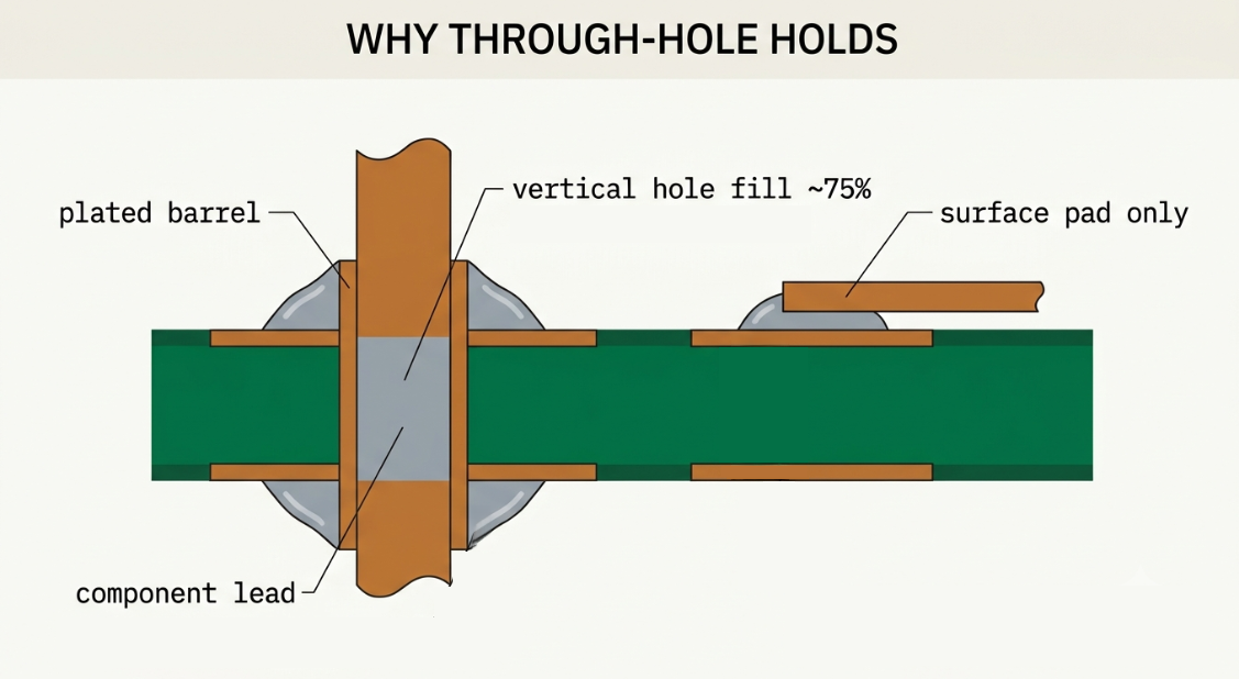
Through-hole leads soldered into drilled holes vs SMD joints on surface copper pads.
The Short Answer
If you are designing something as a prototype, use SMD by default. Drop to through-hole only where it feels the part has to suffer mechanical stress or handle high power. Surface-mount parts are smaller, cheaper, and easier to assemble in volume. That is why you see: the vast majority of components on a typical consumer board are SMD. Through-hole earns its place on connectors, power devices, and anything that goes under vibrations.
That’s the surface-mount vs through-hole debate in two sentences.
What Is Through-Hole Technology?
Through-hole technology (THT) mounts a component by pushing its metal leads through drilled holes and soldering them on the opposite side. The solder doesn’t just sit on the surface; it fills the plated barrel, wrapping metal around metal.
A through-hole joint is anchored through the board, so load is shared by the plated wall rather than a thin surface bond. It is the oldest mainstream mounting method and still the most robust. THT parts are soldered in three ways:
- Wave soldering — the board passes over a wave of molten solder that fills every hole in one sweep. Fast for volume, but it constrains layout.
- Selective soldering — a nozzle that sells specific joints, used when only a few THT parts sit on an otherwise SMD board.
- Hand soldering — an iron, one joint at a time. Slow, but unbeatable for prototypes, repairs, and education.
For plated-through-hole joints, IPC-A-610 specifies a minimum vertical hole fill of around 75% for Class 2 general-purpose electronics and full fill for Class 3 high-reliability work. That requirement is exactly why THT joints are hard to get wrong mechanically: there is a lot of anchored metal in every one. The copper ring around each hole matters too; see our guide on the annular ring for why that pad width is a reliability spec.
What Is Surface-Mount (SMD/SMT)?
Surface-mount devices (SMD) sit on top of the board, soldered to flat copper pads with no leads passing through. A stencil deposits solder paste, a pick-and-place machine drops the parts, and a reflow oven melts the paste to form all the joints at once. No holes, no leads to trim. And the best part is you can use both sides for part placement and soldering.
This is where one piece of jargon trips people up.
SMD vs SMT — they are not the same word.
SMD (Surface-Mount Device) refers to a physical component, such as a 0402 resistor, a QFN, or a tiny LED.
SMT (Surface-Mount Technology) is the process that assembles components, including stencil, placement, and reflow.
You place SMDs using SMT. So “tht vs smt” compares the two processes; “smd vs through hole” compares the parts. Same trade-off, different noun, and getting it right in a DFM email saves confusion.
Reflow is what makes SMD economical: thousands of joints form in a single thermal cycle, and modern lines place tens of thousands of parts per hour. That throughput is the real reason surface mount took over. Not because of the parts, but the machines that place them.
Through-Hole vs SMD: Side-by-Side
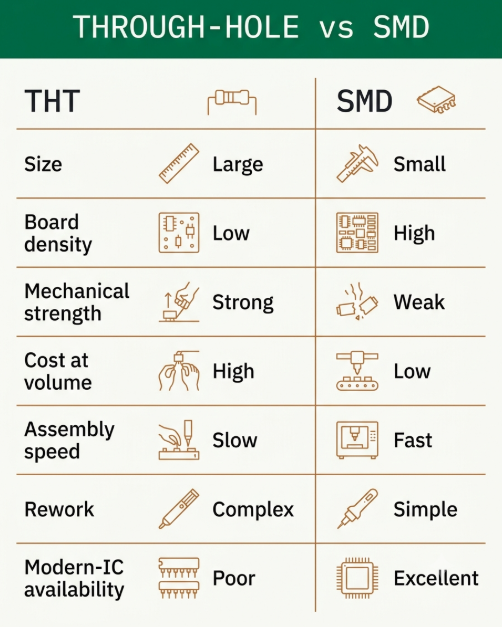
Here is the money table — the SMD vs through hole comparison most people come here for. Use it as a fast lookup, then read the three sub-sections for the “why” behind the rows that matter.
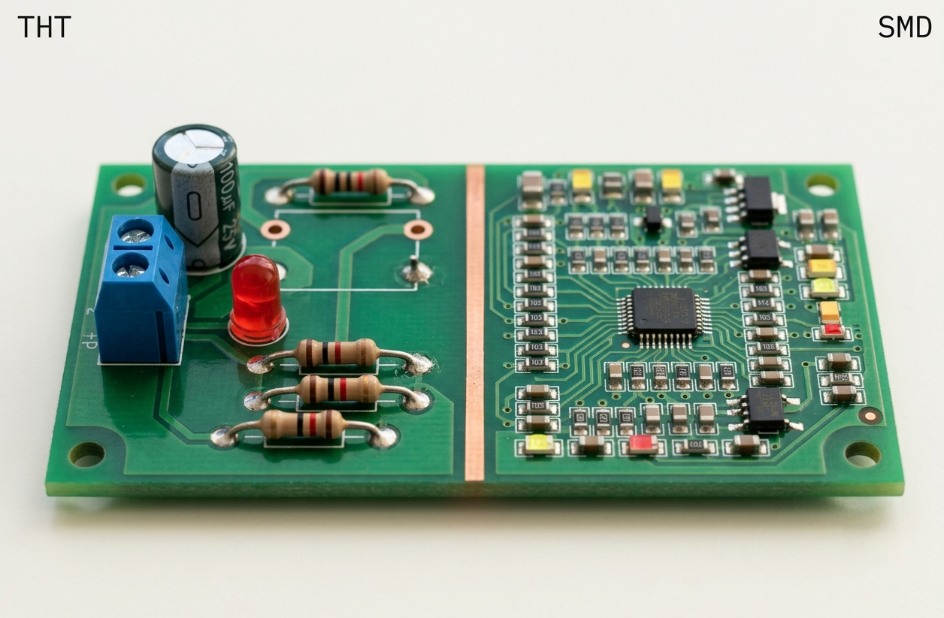
Both SMD passives and through-hole connectors on the same PCB — the typical mixed-technology board.
| Factor | Through-Hole (THT) | Surface-Mount (SMD) |
|---|---|---|
| Component size | Larger, leaded packages | Down to 0402 / 0201 and smaller |
| Board density | Lower — holes block routing | High — both sides usable, tighter pitch |
| Mechanical strength | Excellent — leads anchored in barrel | Good, but a joint is a surface bond only |
| Cost at volume | Higher (slower assembly) | Lower (fully automated) |
| Assembly speed | Slow — wave/selective/hand | Very fast — pick-and-place + reflow |
| Rework | Easy by hand with an iron | Needs a hot air/rework station |
| Availability of modern ICs | Shrinking — many parts SMD-only | Broadest — new silicon lands here first |
| High-frequency / RF behavior | Longer leads add parasitics | Short paths, lower parasitics — better |
Mechanical strength
This is the row that keeps the through-hole alive. A through-hole lead is soldered inside a plated barrel that runs through the entire thickness of the PCB. That means a pull on a connector is resisted by a cylinder of metal surrounding the lead, not just a thin solder fillet attached to a surface pad. It’s one of the biggest reasons that through-hole components handle mechanical stress so well.
An SMD joint bonds only to a surface pad. Pull hard enough, and the pad can lift off the laminate (a “lifted pad”) before the solder fails. That is why USB jacks, barrel connectors, headers, relays, and transformers stay through-hole even on all-SMD boards. If a part gets plugged, unplugged, or shaken, default it to THT.
Cost and assembly speed
The cost story is all about the assembly line, not about the part. Once a pick-and-place machine is set, the part placement becomes very affordable. And the SMT assembly cost per joint collapses as volume rises. Through-hole parts are wave-soldered or hand-soldered, and both are slower.
At prototype quantities, hand-soldering a few THT parts can be cheaper than stencil and machine setup for a full SMT run. As volume climbs, SMDs’ per-unit economics win decisively.
Size and routing density
SMD is the only way to hit modern density. Passives shrink to 0402, 0201, and beyond; you place parts on both sides; and fine-pitch packages fan out hundreds of pins in a small footprint. Via-in-pad squeezes routing under a BGA that through-hole could never touch.
The scale is genuinely different; a 0402 resistor is roughly a millimeter long, versus a leaded resistor’s ten-plus. If you’re unsure which package code maps to which physical size, see our guide on SMD package sizes. When board area is the limiting factor, the through-hole vs. SMD debate is pretty much over with the SMT process.
When Through-Hole Still Wins
Through-hole is not legacy tech; it is the right tool for specific jobs. Reach for it when:
- Connectors and mechanical interfaces: USB, barrel jacks, headers, terminal blocks, card edges, anything plugged or cabled.
- Power and heat: Large electrolytics, high-wattage resistors, power inductors, and transformers benefit from the extra lead cross-section.
- Prototyping and education: THT parts are easy to hand-solder, breadboard, and rework.
- High-vibration environments: Automotive, aerospace, and industrial gear where a lifted SMD pad is a field failure.
The common thread is mechanical stress. If a part must hold up under force, vibration, or thermal cycling, through-hole earns its slower assembly.
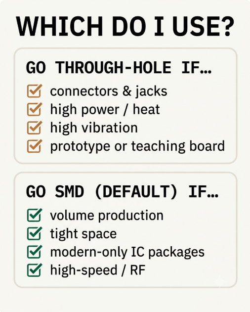
A visual decision guide: reach for SMD by default; drop to through-hole when mechanical stress demands it.
When SMD Is the Default
For everything else, SMD is increasingly the only answer. Choose surface mount when:
- You’re building at volume. Automated placement and reflow make SMD dramatically cheaper per unit past prototype quantities.
- Space is tight. Wearables, handhelds, dense multi-layer designs. SMD is the only way to fit the parts.
- You need modern silicon. New microcontrollers, RF front-ends, power-management ICs, and sensors ship only in SMD packages like QFN, BGA, and LGA.
- You care about signal integrity. Shorter leads mean lower parasitic inductance and capacitance.
Mixing Both SMD and Through-Hole on One Board
Most production boards are mixed-technology. You will see mostly SMD, with a handful of through-hole connectors and power parts. Doing this cleanly is a design-for-manufacturing (DFM) problem, and the assembly order is what you design around.
The typical soldering flow of mixed SMD and through-hole parts:
- Reflow first, then wave or selective solder: SMD parts reflow; through-hole parts are soldered afterward, because a finished reflow board can’t return to the oven without disturbing joints.
- Keep THT parts on one side: If all through-hole leads exit the same face, wave soldering stays simple. Parts on both sides require selective soldering or handwork.
- Protect SMD parts during wave: Bottom-side SMDs near a wave path need adhesive or careful layout.
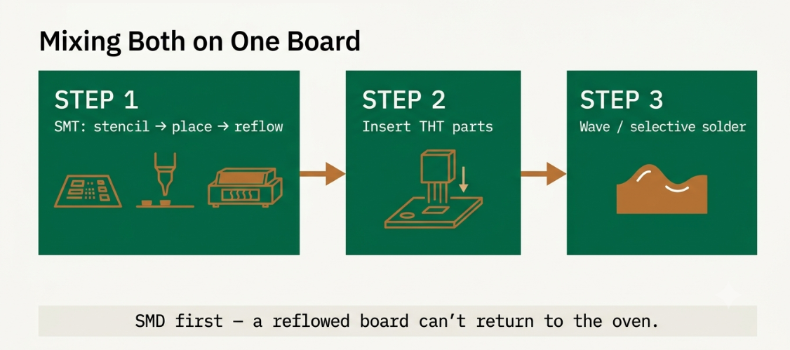
The standard mixed-board process: SMD reflow first, wave or selective solder for through-hole parts after.
The practical rule: minimize the number of distinct solder processes your board needs. Every extra process adds cost and handling. One or two THT connectors are normal; a dozen scattered THT parts on an SMD board is a DFM smell worth questioning. For how board thickness interacts with THT plating and lead length, see our note on standard PCB thickness.
Through-Hole vs SMD LEDs
LEDs are the one component where the SMD vs. through-hole LED choice is genuinely a coin toss for hobbyists, so it deserves its own verdict.
Through-hole LEDs — the classic 3 mm and 5 mm domes are indicators. They’re easy to hand-solder, easy to see, and suitable for status lights, beginner projects, and anything poking through an enclosure. The dome acts as a built-in lens with a narrow field of view.
SMD LEDs — packages like 0603, 2835, 3528, and 5050 are for lighting and density. They’re flat, come in high brightness and wide viewing angles, and dominate LED strips, backlights, panel lighting, and RGB arrays.
The rule of thumb says: through-hole LEDs for indicators you look “at”; SMD LEDs for lighting you see “by”.
Frequently Asked Questions
Is SMD better than through-hole?
For most modern designs, yes. Because SMD is smaller, cheaper at volume, and machine-assembled, it dominates consumer and industrial boards. Through-hole still wins for mechanical strength, high power, and high-vibration parts.
Why is through-hole stronger than SMD?
A through-hole lead is soldered into a plated barrel running the full board thickness, so the load is anchored by metal wrapped around the hole. An SMD joint bonds only to a flat surface pad, which can lift off the laminate under enough force. The barrel gives THT its physical edge.
Can you mix SMD and through-hole on one PCB?
Yes, most of the real boards do exactly this. SMD parts are reflowed first, then through-hole parts are soldered. High-power ones are used as through-hole components.
Are through-hole components obsolete?
Through-hole is a shrinking share of parts on a typical board, but it is not going away where physics demands it. For example: connectors, large electrolytics, power inductors, transformers, and terminal blocks remain through-hole by design because they handle real power.
What is the difference between SMT and SMD?
SMT (Surface-Mount Technology) is the process that covers stencil printing, pick-and-place, and reflow. SMD (Surface-Mount Device) is the physical component that is assembled. So, one is the process, the other is the part.
Are SMD LEDs better than through-hole LEDs?
SMD LEDs are flat, bright, and wide-angle. They are ideal for lighting, strips, backlights, and compact panels. On the other hand, through-hole LEDs are easier to hand-solder and make cleaner indicators through a panel hole.
The Bottom Line
The real skill isn’t picking a camp randomly; it’s reading each part correctly. Silicon and passives default to SMD; anything plugged, powered hard, or shaken defaults to through-hole. The art is to mix the two without adding an extra solder process to the board. Think part-by-part instead of board-wide, and the choice stops being a debate and becomes a checklist. (If the terms board and assembly blur together, our PCB vs PCBA explainer draws the line.)
If you found this guide helpful, you’ll probably enjoy our other PCB design resources. We publish practical, engineer-written articles covering topics such as standard PCB thickness, PCB vs. PCBA, through-hole vs. SMD components, and SMD package sizes.
If you’re building hardware and need technically accurate content for your company, we also create engineering blogs, application notes, and educational resources written by working PCB engineers.
Our goal is to help electronics companies publish content that engineers actually trust and search engines reward. Want to see the difference engineer-written content can make? Start with a free pilot article of up to 1,200 words, tailored to your website and written by working PCB engineers. More about how we work: services & pricing.